Automatic tool changer for machining center
Electronic drum type

36.1 Product Introduction
36.1.1 Contents
36.1.2 Specifications
|
No. |
Item |
Specification |
|
|
1 |
Max. tool diameter |
Full tool |
Ø95mm |
|
Adjacent empty tool |
Ø15mm |
||
|
|
Max. tool weight |
8 KG |
|
|
3 |
Max. tool capacity |
20 T |
|
|
4 |
Tool magazine weight (including ATC) |
280KG |
|
|
5 |
Tool change time |
1.8sec |
|
|
6 |
Tool indexing time |
0.7sec/60HZ; 0.9sec/50HZ |
|
|
7 |
Tool selection |
Shortest route tool selection |
|
|
8 |
Environmental temperature/humidity for operation |
0~40°C/20~90%RH No condensation |
|
|
No. |
Item |
Specification |
|
|
1 |
Max. tool diameter |
Full tool |
Ø95mm |
|
Adjacent empty tool |
Ø15mm |
||
|
|
Max. tool weight |
8 KG |
|
|
3 |
Max. tool capacity |
24 T |
|
|
4 |
Tool magazine weight (including ATC) |
38280KG |
|
|
5 |
Tool change time |
1.8sec |
|
|
6 |
Tool indexing time |
1.3sec/60HZ; 0.9sec/50HZ |
|
|
7 |
Tool selection |
Shortest route tool selection |
|
|
8 |
Environmental temperature/humidity for operation |
0~40°C/20~90%RH No condensation |
|
36.1.3 Overview of tool magazine structure
(a) Contour dimension drawing for tool magazine (SDK40BT2053075S00R-1)

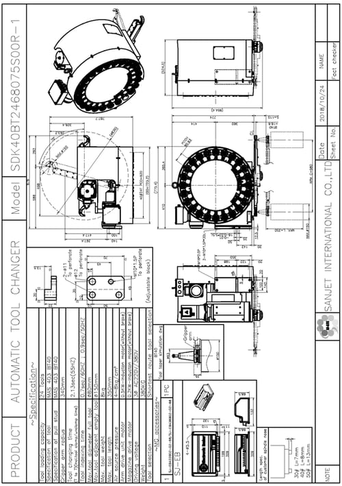
(b) Contour dimension drawing for tool magazine (SDK40BT2468075S00R-1)
(c) Configuration drawing of tool magazine and machine center (sample)

36.1.4 Component assembly drawing for tool pot

|
Item |
Material No. |
Name |
Q’ty |
Remarks |
|
1 |
DA0100202 |
40# Tool draw lump |
1 |
|
|
2 |
DA0100301 |
Spring |
4 |
BT |
|
3 |
DA0400302 |
Spring |
4 |
CAT |
|
4 |
DA0103202 |
401 (60°) Tool hold |
1 |
60° |
|
5 |
DA0103401 |
401 *(90°) Tool hold |
1 |
90° |
|
6 |
DA0103302 |
401 Heavy-nut |
2 |
|
|
7 |
DA0300103 |
Tool pot pulley |
1 |
|
|
8 |
DA0300301 |
Tool pot regular axle |
1 |
|
|
9 |
CE08 |
Tool pot support wheel |
1 |
BT |
|
CE06 |
B Tool pot axle of the pulley |
1 |
CAT |
|
|
10 |
MS05100045 |
M5*45L Z Crosshed self drilling bolt |
4 |
|
(a) Component assembly drawing for tool pot

|
Item |
Material No. |
Name |
Q’ty |
Remarks |
|
1 |
DA0103202 |
401 *(60°) Tool hold |
1 |
60° |
|
2 |
DA0103401 |
401 *(90°) Tool hold |
1 |
90° |
|
3 |
DA0103302 |
401 Heavy-nut |
2 |
|
|
4 |
DA0300103 |
Tool pot pulley |
1 |
|
|
5 |
DA0300301 |
Tool pot regular axle |
1 |
|
|
6 |
DA0300404 |
Tool pot support wheel |
1 |
|
|
7 |
DA0301302 |
B Tool pot axle of the pulley |
1 |
|
|
8 |
DA0400101 |
DIN 40 Tool draw lump |
1 |
DIN |
|
9 |
DA0400202 |
DIN Block |
1 |
DIN |
|
10 |
DA0400302 |
Spring |
4 |
|
|
11 |
CE06 |
M5*45L Crosshed self drilling bolt |
4 |
|
(b) Assembly drawing for tool disk component

|
Item |
Material No. |
Name |
Q’ty |
Remarks |
|
1 |
D4B-C0 |
BT (60°) Tool pot component |
24 |
60°-BT |
|
D4B-C1 |
BT (90°) Tool pot component |
24 |
90°-BT |
|
|
D4C-C0 |
CAT (60°) Tool pot component |
24 |
60°-CAT |
|
|
D4C-C1 |
CAT (90°) Tool pot component |
24 |
90°-CAT |
|
|
D4D-C0 |
DIN (60°) Tool pot component |
24 |
60°-DIN |
|
|
D4D-C1 |
DIN (90°) Tool pot component |
24 |
90°-DIN |
|
|
2 |
DE0112903 |
BT (90°) Tool pot component |
24 |
|
|
3 |
DE0116603 |
CAT (60°) Tool pot component |
1 |
|
|
4 |
BA32008 |
CAT (90°) Tool pot component |
2 |
|
|
5 |
MF10150 |
DIN (60°) Tool pot component |
24 |
|
|
6 |
MI06100040 |
DIN (90°) Tool pot component |
24 |
|
(c) Assembly drawing for driving component

|
Item |
Material No. |
Name |
Q’ty |
Remarks |
|
1 |
D4B-C0 |
BT (60°) Tool pot component |
20 |
60°-BT |
|
D4B-C1 |
BT (90°) Tool pot component |
20 |
90°-BT |
|
|
D4C-C0 |
CAT (60°) Tool pot component |
20 |
60°-CAT |
|
|
D4C-C1 |
CAT (90°) Tool pot component |
20 |
90°-CAT |
|
|
D4D-C0 |
DIN (60°) Tool pot component |
20 |
60°-DIN |
|
|
D4D-C1 |
DIN (90°) Tool pot component |
20 |
90°-DIN |
|
|
2 |
DE0105506 |
20T# Rotation disk |
1 |
|
|
3 |
DE0112902 |
CF10 Shanked bearing |
20 |
|
|
4 |
BA32008 |
NO. 32008 Bearing |
2 |
|
|
5 |
MF10150 |
M10*1.5P Flange nut |
20 |
|
|
6 |
MI06100040 |
M6*1.0P*40L CAP |
20 |
|
(d) Assembly drawing for arm component

|
Item |
Material No. |
Name |
Q’ty |
Remarks |
|
1 |
DC0100114 |
lDriving seat |
1 |
|
|
2 |
DC0100305 |
Cam |
1 |
24T |
|
DC0101503 |
20T Cam |
1 |
20T |
|
|
3 |
DC0100402 |
Cam shaft |
1 |
|
|
4 |
DC0100603 |
Sensor fixed slice |
1 |
|
|
5 |
DC0101403 |
Bearing cover |
1 |
|
|
6 |
DC0104501 |
Sensor block-A |
1 |
|
|
7 |
DC0104601 |
Sensor block-B |
1 |
|
|
8 |
DC0104701 |
Driving gear-B |
2 |
|
|
9 |
BA30204 |
NO. 30204 Bearing |
2 |
|
|
10 |
BA6003 |
NO.6003ZZ Bearing |
1 |
|
|
11 |
CO018 |
Ø18 C shape buckled ring |
3 |
|
|
12 |
ID1820R02L0101 |
1/4HP-0.2KW Moter |
1 |
|
|
13 |
IMB12-04BPSVCOS |
M12 SENSOR |
2 |
|
|
14 |
IME12-N+W |
M12 SENSOR Nut + Washer |
4 |
|
|
15 |
KE050525 |
5*5*25L Double rounded key |
2 |
|
|
16 |
KE080750 |
8*7*50L Double rounded key |
2 |
|
|
17 |
MA05080005 |
M5*0.8P*5L Socket blot |
4 |
|
|
18 |
MIS05080012 |
M5*0.8P*12L CAP + Spring washer |
4 |
|
|
19 |
MISW08125030 |
M8*1.25P*30L CAP+ CAP + Spring washer + Washer |
4 |
|
|
20 |
MC05080008 |
M5*0.8P*8 Semi-rounded bolt |
4 |
|
(e) Assembly drawing for arm component

|
Item |
Material No. |
Name |
Q’ty |
Remarks |
|
1 |
DB0100203 |
Driven cover |
2 |
|
|
2 |
DB0100303 |
Driven pin |
2 |
|
|
3 |
DB0100502 |
Position pin |
2 |
|
|
4 |
DB0100605 |
Spanded tighted cover |
1 |
|
|
5 |
DB0100701 |
Driven pin spring |
2 |
|
|
6 |
DB0100802 |
Sliding spring |
2 |
|
|
7 |
DB0100402 |
BT-60° Position key |
2 |
60°-BT |
|
DB0100903 |
BT-65° Position key |
2 |
65°-BT |
|
|
DB0101103 |
BT-75° Position key |
2 |
75°-BT |
|
|
DB0101503 |
CAT/DIN 75° Position key |
2 |
75° CAT/DIN |
|
|
8 |
DB0101401 |
680 Sliding block |
2 |
|
|
9 |
DB0700604 |
DIN680 Arm |
1 |
DIN |
|
DB0700108 |
BT680 Arm |
1 |
BT |
|
|
10 |
DB0700202 |
680 Sliding cover |
2 |
680 |
|
11 |
DB0700302 |
680 Stopping rod |
2 |
680 |
|
12 |
MH601 |
M6 Straight graspe |
2 |
|
|
13 |
YB4045 |
40*45 Spanded washer |
3 |
|
|
14 |
DU101210 |
Ø10*Ø12*10 Self-lubricated bearing |
2 |
|
|
15 |
NUT08125008 |
M8*1.25P*8L Nut |
2 |
|
|
16 |
MB05080010 |
M5*0.8P*10L Countersink bolt |
18 |
|
|
17 |
MI05080016 |
M5*0.8P*16L CAP |
8 |
|
|
18 |
MI08125035 |
M8*1.25P*35L CAP |
4 |
|
|
19 |
W08 |
M8 Washer |
2 |
|
|
20 |
WI08 |
M6 Conical spring washer |
6 |
|
(f) Assembly drawing for arm component

|
Item |
Material No. |
Name |
Q’ty |
Remarks |
|
1 |
D4B400205 |
40 Driven pin |
2 |
|
|
2 |
D4B400301 |
40 Slip pipe |
2 |
|
|
3 |
D4B400405 |
40 Sliding block |
2 |
|
|
4 |
D4B400503 |
40 Driven cover |
2 |
|
|
5 |
D4B401007 |
BT40 Placement tool seat |
2 |
BT |
|
D4B401109 |
CAT/DIN40 Placement tool seat |
2 |
CAT/DIN |
|
|
6 |
D4B401202 |
M1 Driven pin cover |
2 |
|
|
7 |
D4B401304 |
M6 Position pin |
2 |
|
|
8 |
D4B800203 |
40560 Stopping rod |
2 |
560 |
|
D4B500205 |
40620 Stopping rod |
2 |
620 |
|
|
9 |
D4B800503 |
560 Detachable arm |
1 |
560 |
|
D4B500406 |
620 Detachable arm |
1 |
620 |
|
|
10 |
DB0100605 |
40 Spanded tighted cover |
1 |
|
|
12 |
DB0102301 |
530 Sliding spring |
2 |
|
|
13 |
DB0103302 |
530 Driven pin spring |
2 |
60°-BT |
|
DB0103601 |
60° (BT) Position key |
2 |
65°-BT |
|
|
DB0103704 |
65°(BT) Position key |
2 |
75°-BT |
|
|
DB0104603 |
60°/90° (CAT/DIN) Position key |
|
60°/90° CAD/DIN |
|
|
DB0104303 |
65° (CAT/DIN) Position key |
2 |
65° CAD/DIN |
|
|
DB0103504 |
75° (CAT/DIN) Position key |
2 |
75° CAD/DIN |
|
|
14 |
A1-101807 |
Ø10*Ø18*7 Dustproof oil seal |
2 |
|
|
15 |
A1-142207 |
Ø14*Ø22*7 Dustproof oil seal |
2 |
|
|
16 |
DU101210 |
Ø10*Ø12*10L Self-lubricated bearing |
2 |
|
|
17 |
DU141610 |
Ø14*Ø16*10L Self-lubricated bearing |
4 |
|
|
18 |
EFPSM25 |
O-Ring |
2 |
|
|
19 |
M601 |
Straight graspe |
2 |
|
|
20 |
YB4045 |
40*4 Spanded washer |
3 |
|
|
21 |
NUT8125008 |
M8*1.25P*8L NUT |
2 |
|
|
22 |
MA08125010 |
M8*1.25P*10L Socket bolt |
4 |
|
|
23 |
MB05080008 |
M5*0.8P*8L Countersink bolt |
2 |
BT |
|
MB05080010 |
M5*0.8P*10L Countersink bolt |
2 |
CAT/DIN |
|
|
24 |
MI05080016 |
M5*0.8P*16L CAP |
16 |
|
|
25 |
MI08125035 |
M8*1.25P*35L CAP |
4 |
|
|
26 |
MC05080008 |
M5*0.8P*8L Semi-rounded bolt |
2 |
|
|
27 |
WI08 |
M8 Conical Spring Washer |
2 |
|
|
28 |
WS08148040 |
M8 Spring washer |
4 |
|
(g) Assembly drawing for arm component

|
Item |
Material No. |
Name |
Q’ty |
Remarks |
|
1 |
D4B400205 |
40 Driven pin |
2 |
|
|
2 |
D4B400301 |
40 Slip pipe |
2 |
|
|
3 |
D4B400503 |
40 Driven cover |
2 |
|
|
4 |
D4B300506 |
500 Detachable arm |
1 |
500 |
|
D4B400906 |
530 Detachable arm |
1 |
530 |
|
|
5 |
D4B401007 |
BT40 Placement tool seat |
2 |
BT |
|
D4B401109 |
CAT/DIN Placement tool seat |
2 |
CAT/DIN |
|
|
6 |
D4B401202 |
M1 Driven pin cover |
2 |
|
|
7 |
D4B401304 |
6 Position pin |
2 |
|
|
8 |
D4B300902 |
40500 Sliding block |
2 |
500 |
|
D4B403003 |
40530 Sliding block |
2 |
530 |
|
|
9 |
DB0100605 |
40 Spanded tighted cover |
1 |
|
|
10 |
DB0102301 |
Sliding spring |
2 |
|
|
11 |
DB0103302 |
Driven pin spring |
2 |
|
|
12 |
DB0103601 |
60° (BT) Position key |
2 |
60°-BT |
|
DB0103704 |
65° (BT) Position key |
2 |
65°-BT |
|
|
DB0103802 |
75° (BT) Position key |
2 |
75°-BT |
|
|
DB0104303 |
65° (CAT/DIN) Position key |
2 |
65° CAT/DIN |
|
|
DB0103504 |
75° (CAT/DIN) Position key |
2 |
75° CAT/DIN |
|
|
13 |
A1-101807 |
Ø10*Ø18*7 Dustproof oil seal |
2 |
|
|
14 |
A1-142207 |
Ø14*Ø22*7 Dustproof oil seal |
2 |
|
|
15 |
DU101210 |
Ø10*Ø12*10L Self-lubricated bearing |
2 |
|
|
16 |
DU141610 |
Ø14*Ø16*10L Self-lubricated bearing |
4 |
|
|
17 |
EFPSM25 |
S25 O-Ring |
2 |
|
|
18 |
MH601 |
M6 Straight graspe |
2 |
|
|
19 |
YB4045 |
40*45 Spanded washer |
3 |
|
|
20 |
MA08125010 |
M8*1.25P*10L Socket bolt |
4 |
|
|
21 |
MB05080010 |
M5*0.8P*10L Countersink bolt |
2 |
|
|
22 |
MI05080012 |
M5*0.8P*12L CAP |
8 |
|
|
23 |
MI05080016 |
M5*0.8P*16L CAP |
8 |
|
|
24 |
MI08125035 |
M8*1.25P*35L CAP |
4 |
|
|
25 |
MC05080008 |
M5*0.8P*8L Semi-rounded bolt |
2 |
|
|
26 |
WI08 |
M8 Conical spring washer |
4 |
|
(h) Assembly drawing for model component

|
Item |
Material No. |
Name |
Q’ty |
Remarks |
|
1 |
DE0118001 |
40#24T-R 140L Main body |
1 |
|
|
DE0118601 |
40#24T-R 128L Main body |
1 |
50075 50080 |
|
|
DE0105217 |
40#24T-R 120L Main body |
1 |
50070 50090 62055(RH) |
|
|
DE0105807 |
40#24T-R 140L Main body |
1 |
53070 |
|
|
2 |
DE0100316 |
20/24T-R Tool down claw |
1 |
|
|
3 |
DE0100504 |
Tool pot position seat |
1 |
|
|
4 |
DE0100606 |
Air cylinder pushing shaft |
1 |
|
|
5 |
DE0100701 |
Tool down connecting shaft |
1 |
|
|
6 |
DE0100802 |
Air cylinder connecting shaft |
1 |
|
|
7 |
DE0100901 |
Tool down claw connecting shaft |
1 |
|
|
8 |
DE0101004 |
Pushing shaft position pin |
1 |
|
|
9 |
DE0101102 |
Connecting pin |
1 |
|
|
10 |
DE0101503 |
Disk spindle |
1 |
|
|
11 |
DE0101802 |
Origin sensor fixed slice |
1 |
|
|
12 |
DE0102504 |
Air cylinder position pin |
1 |
|
|
13 |
DE0107003 |
Tool down sensor slice |
1 |
|
|
14 |
DE0107104 |
Tool down sensor seat |
1 |
|
|
15 |
DE0116901 |
Air cylinder joint-C |
1 |
|
|
16 |
DE0117001 |
Air cylinder |
1 |
|
|
17 |
DE0117201 |
Tool down claw pressing plate-B |
2 |
|
|
18 |
NP137-008-R01 |
(1/4PT) 10mm Elbow connection |
2 |
|
|
19 |
CO012 |
Ø12C81o C shape buckled ring |
3 |
|
|
20 |
IME12-04BPSZCOS |
M12 SENSOR |
1 |
|
|
21 |
M12 SENSOR Washer |
M12 SENSOR Washer c/j] |
2 |
|
|
22 |
M12 SENSOR NUT |
M12 SENSOR Nut |
2 |
|
|
23 |
MUW08125 |
M8*1.25PU8 l U type unt |
2 |
|
|
24 |
MA06100006 |
M6*1.0P*6L Socket bolt |
1 |
|
|
25 |
MP08125040 |
M8*1.250P*40L Socket bolt |
2 |
|
|
27 |
MI06100016 |
M6*1.0P*16L CAP |
8 |
|
|
28 |
MI06100035 |
M6*1.0P*35L CAP |
1 |
|
|
29 |
MIS06100020 |
M6*1.0P*20L CAP CAP + Spring washer |
6 |
|
|
30 |
MI08100035-NL |
M8*1.0P*35L CAP |
1 |
|
|
31 |
MI08100035 |
M8*1.0P*35L CAP |
2 |
|
|
32 |
MI08125070 |
M8*1.25P*70L CAP |
1 |
|
|
33 |
MISW10150040 |
M10*1.5P*40L CAP CAP + Spring washer + Washer |
1 |
|
|
34 |
WS06125015 |
M6*12.5*1.5 Washer |
2 |
|
|
35 |
WS08148040 |
M8 Spring washer |
1 |
|
|
36 |
W0818020 |
M8*18*2t Washer |
1 |
|
|
37 |
WI16 |
M16 Conical spring washer |
1 |
|
(i) Assembly drawing for model component

|
Item |
Material No. |
Name |
Q’ty |
Remarks |
|
1 |
DE0117601 |
40#24T-R 156L Main body |
1 |
53075 |
|
2 |
DE0100316 |
20/24T-R Tool down claw |
1 |
|
|
3 |
DE0100504 |
Tool pot position seat |
1 |
|
|
4 |
DE0100606 |
Air cylinder pushing shaft |
1 |
|
|
5 |
DE0100701 |
Tool down connecting shaft |
1 |
|
|
6 |
DE0100802 |
Air cylinder connecting shaft |
1 |
|
|
7 |
DE0100901 |
Tool down claw connecting shaft |
1 |
|
|
8 |
DE0101004 |
Pushing shaft position pin |
1 |
|
|
9 |
DE0101102 |
Connecting pin |
1 |
|
|
10 |
DE0101503 |
Disk spindle |
1 |
|
|
11 |
DE0101802 |
Origin sensor fixed slice |
1 |
|
|
12 |
DE0102504 |
Air cylinder position pin |
1 |
|
|
13 |
DE0107003 |
Tool down sensor slice |
1 |
|
|
14 |
DE0107104 |
Tool down sensor seat |
1 |
|
|
15 |
DE0116901 |
C Air cylinder joint-C |
1 |
|
|
16 |
DE0117001 |
Air cylinder |
1 |
|
|
17 |
DE0117201 |
Tool down claw pressing plate-B |
2 |
|
|
18 |
NP137-008-R01 |
(1/4PT) 10mm Elbow connection |
2 |
|
|
19 |
CO012 |
Ø12C81o C shape buckled ring |
3 |
|
|
20 |
IMB12-04BPSVCOS |
M12 SENSOR |
1 |
|
|
21 |
M12 SENSOR Washer |
M12 SENSOR Washer c/j] |
2 |
|
|
22 |
M12 SENSOR NUT |
M12 SENSOR Nut l |
2 |
|
|
23 |
MUW08125 |
M8*1.25PU8 l U type unt |
2 |
|
|
24 |
MA06100006 |
M6*1.0P*6LJ Socket bolt |
1 |
|
|
25 |
MP08125040 |
M8*1.250P*40L Socket bolt |
2 |
|
|
26 |
MI06100016 |
M6*1.0P*16L CAP |
8 |
|
|
27 |
MI06100035 |
M6*1.0P*35L CAP |
1 |
|
|
28 |
MIS06100020 |
M6*1.0P*20L CAP+Spring washer |
6 |
|
|
29 |
MI08100035-NL |
M8*1.0P*35L CAP |
1 |
|
|
30 |
MI08100035 |
M8*1.0P*35L CAP |
2 |
|
|
31 |
MI08125070 |
M8*1.25P*70L CAP |
1 |
|
|
32 |
MISW10150040 |
M10*1.5P*40L CAP + Spring washer + Washer |
1 |
|
|
33 |
WS06125015 |
M6*12.5*1.5 Washer |
2 |
|
|
34 |
WS08148040 |
M8 Spring washer |
1 |
|
|
35 |
W0818020 |
M8*18*2 Washer |
1 |
|
|
36 |
WI16 |
M16 Conical spring washer |
1 |
|
(j) Assembly drawing for cable box component

|
Item |
Material No. |
Name |
Q’ty |
Remarks |
|
1 |
DE0102609 |
Wire box |
1 |
|
|
2 |
DE0102704 |
Wire box cover |
1 |
|
|
3 |
DE0106004 |
Wire box seat-B |
1 |
|
|
4 |
DE0109101 |
Wire box shim |
1 |
|
|
5 |
K3E200403 |
Double coil solenoid valve |
1 |
|
|
6 |
PG11 |
PGB 11 Wire fixed joint |
5 |
|
|
7 |
SJ-D1404 |
SDK Terminal block |
1 |
|
|
8 |
MI04070025 |
M4*0.7P*25L CAP |
2 |
|
|
9 |
MI0508008 |
M5*0.8P*8L CAP |
4 |
|
|
10 |
MC0508008 |
M5*0.8P*8L Semi-rounded bolt |
2 |
|
|
11 |
MC06100010-Z |
M6*1.0P*10L Semi-rounded bolt |
4 |
|
(k) Assembly drawing for tool magazine

|
Item |
Material No. |
Name |
Q’ty |
Remarks |
|
1 |
D4B-C0 |
BT-60° Tool pot component |
20/24 |
BT-60° |
|
D4B-C1 |
BT-90° Tool pot component |
20/24 |
BT-90° |
|
|
D4C-C0 |
CAT-60° Tool pot component |
20/24 |
CAT-60° |
|
|
D4C-C1 |
CAT-90° Tool pot component |
20/24 |
CAT-90° |
|
|
D4D-C0 |
DIN-60° Tool pot component |
20/24 |
DIN-60° |
|
|
D4D-C1 |
DIN-90° Tool pot component |
20/24 |
DIN-90° |
|
|
2 |
D401B20-C0 |
20T-BT (60°) Rotating disk component |
1 |
20T-BT |
|
D401B20-C1 |
20T-BT (90°) Rotating disk component |
1 |
20T-BT |
|
|
D401C20-C0 |
20T-CAT (60°) Rotating disk component |
1 |
20T-CAT |
|
|
D401C20-C1 |
20T-CAT (90°) Rotating disk component |
1 |
20T-CAT |
|
|
D401D20-C0 |
20T-DIN (60°) Rotating disk component |
1 |
20T-DIN |
|
|
D401D20-C1 |
20T-DIN (90°) Rotating disk component |
1 |
20T-DIN |
|
|
D401B24-CL0 |
24T-BT (60°) Rotating disk component |
1 |
24T-BT |
|
|
D401B24-CL1 |
24T-BT (90°) Rotating disk component |
1 |
24T-BT |
|
|
D401C24-CL0 |
24T-CAT (60°) Rotating disk component |
1 |
24T-CAT |
|
|
D401C24-CL1 |
24T-CAT (90°) Rotating disk component |
1 |
24T-CAT |
|
|
D401D24-CL0 |
24T-DIN (60°) Rotating disk component |
1 |
24T-DIN |
|
|
D401D24-CL1 |
24T-DIN (90°) Rotating disk component |
1 |
24T-DIN |
|
|
3 |
D4D-6875 |
DIN-680 Arm component |
1 |
DIN-680 |
|
D4B-6875 |
BT-680 Arm component |
1 |
BT-680 |
|
|
D4B-5675C |
BT-560 Detachable arm component |
1 |
BT-560 |
|
|
D4C-5675C |
CAT/DIN-560 Detachable arm component |
1 |
CAT/DIN 560 |
|
|
D4B-6275C |
BT-620 Detachable arm component |
1 |
BT-620 |
|
|
D4C-6275C |
CAT/DIN-620 Detachable arm component |
1 |
CAT/DIN 620 |
|
|
D4C-5075CW |
CAT/DIN-500 Arm component |
1 |
CAT/DIN 500 |
|
|
D4B-5375CW |
BT-530 Arm component |
|
BT-530 |
|
|
D4C-5375CW |
CAT/DIN-530 Arm component |
1 |
CAT/DIN 530 |
|
|
4 |
D420-C0 |
20T Driving component |
1 |
20T |
|
D424-C0 |
24T Driving component |
1 |
24T |
|
|
5 |
D4E24-101 |
20/24T Model component |
1 |
|
|
D4E24-401 |
20/24T Model component |
1 |
50075 50080 |
|
|
D4E24-801 |
20/24T Model component |
1 |
50070 50090 62055RH |
|
|
D4E24-1001 |
20/24T Model component |
1 |
53700 |
|
|
6 |
DTB4-01- 24V2208-ST |
DK40# Cable box set |
1 |
|
|
7 |
DD0100503 |
Acrylic cover |
1 |
|
|
8 |
DD0100702 |
Arc cover |
1 |
|
|
9 |
DD0107601 |
68075 Arc cam cover |
1 |
68075 |
|
DD0107201 |
56075 Arc cam cover |
1 |
56075 |
|
|
DD0110401 |
62075 Arc cam cover |
1 |
62075 |
|
|
DD0112201 |
50075 Arc cam cover |
1 |
50075 |
|
|
DD0101906 |
53070/75 Arc cam cover |
1 |
53070 53075 |
|
|
10 |
DD0100101 |
Rotation cover |
1 |
20/24 |
|
DD0121001 |
24PVC Rotation cover |
1 |
24 |
|
|
11 |
DE0106004 |
Wire box pedestal |
1 |
|
|
12 |
DE0107301 |
680*758 Cam shim |
2 |
68075 |
|
DE0109201 |
560*758 Cam shim |
2 |
56075 |
|
|
DE0107202 |
620*758 Cam shim |
2 |
62075 |
|
|
DE0104602 |
500*758 Cam shim |
2 |
50075 |
|
|
13 |
DE0101701 |
Origin sensor seat |
1 |
|
|
14 |
490083A22P2G |
8 Cam |
1 |
|
|
15 |
ID2208R55S0101 |
8 Cam motor |
1 |
|
|
16 |
FR12175 |
M12r'pf Ring |
1 |
|
|
17 |
SJM401501401 |
M40*1.5P*14T Nut |
1 |
|
|
18 |
L7B102201 |
Ø8*18L Pin |
2 |
|
|
19 |
MB12175035 |
M12*1.75P*35L Countersink bolt |
4 |
|
|
20 |
MC06100010-Z |
M6*1.0P*10L Semi-rounded bolt |
31 |
|
|
21 |
MCW05080008-Z |
Semi-rounded bolt + Washer |
6 |
|
|
22 |
MI06100010 |
M6*1.0P*10L CAP |
1 |
|
|
23 |
MI06100040 |
M6*1.0P*40L CAP |
20/24 |
|
|
24 |
MI12175045 |
M12*1.75P*45L CAP |
4 |
|
|
25 |
MISW08125030 |
M8*1.25P*30L CAP |
5 |
|
|
26 |
MIW06100012 |
CAP + Spring washer Washer |
2 |
|
|
27 |
W12S |
M6*1.0P*12L CAP + Washer |
4 |
|
|
28 |
01-20 |
M12u4 Thick washer |
1 |
|
|
01-24 |
01-20 Number plaque |
1 |
|
(l) Assembly drawing for tool magazine

|
Item |
Material No. |
Name |
Q’ty |
Remarks |
|
1 |
D4B-B0 |
BT-60° Tool pocket component |
20/24 |
BT-60° |
|
2 |
D401B24-CL0 |
24T-BT (60°) Rotating disk component |
1 |
24T-60° |
|
3 |
D4B-5375CW |
530 Arm component |
1 |
530 |
|
4 |
D420-C0 |
20T Driving component |
1 |
20T |
|
D424-C0 |
24T Driving component |
1 |
24T |
|
|
5 |
D4E24-601 |
53075° 20/24T Model component |
1 |
53075 |
|
6 |
DTB4-01-24V2208-ST |
DK40 Cable box set |
1 |
|
|
7 |
DD0100503 |
R Acrylic cover |
1 |
|
|
8 |
DD0100702 |
R8 Arc cover |
1 |
|
|
9 |
DD0101906 |
53070/75 Arc cam cover |
1 |
53070 53075 |
|
10 |
DD0100101 |
Rotation cover |
1 |
20/24 |
|
DD0121001 |
24PVC Rotation cover |
1 |
24 |
|
|
11 |
DE0106004 |
B Wire box pedestal |
1 |
|
|
12 |
DE0101701 |
Origin sensor seat |
1 |
|
|
13 |
475083A22P2G |
Cam |
1 |
|
|
14 |
ID2208R55S0101 |
Cam motor |
1 |
|
|
15 |
FR12175 |
M12 Ring |
1 |
|
|
16 |
SJM401501402 |
M40*1.5P*14T Nut |
1 |
|
|
17 |
MC06100010-Z |
M6*1.0P*10L Semi-rounded bolt |
27 |
|
|
18 |
MCW05080008-Z |
M5*8L Semi-rounded bolt+Washer |
6 |
|
|
19 |
MI06100010 |
M6*1.0P*10L CAP |
1 |
|
|
20 |
MI06100040 |
M6*1.0P*40L CAP |
20/24 |
|
|
21 |
MI12175045 |
M12*1.75P*45L CAP |
4 |
|
|
22 |
MISW08125030 |
M8*1.25P*30L CAP |
5 |
|
|
23 |
MIW06100012 |
M6*1.0P*12L CAP |
2 |
|
|
24 |
W12S |
M12 Thick washer |
4 |
|
|
25 |
01-20 |
01-20 Number plaque |
1 |
|
|
01-24 |
01-24 Number plaque |
1 |
|
36.2 Circuit Control
36.2.1 Control component
(a) Configuration diagram for component

|
No. |
Control Component |
Function |
Specification |
Q’ty |
|
01 |
Tool up reed sensor |
Tool up |
M12-PNP-NO-4mm |
1 |
|
02 |
Tool pot down |
Tool down |
M12-PNP-NO-4mm |
1 |
|
03 |
Tool counting & position sensor |
Tool counting & position signal |
M12-PNP-NO-4mm |
1 |
|
04 |
Confirmation sensor |
Confirmation signal |
M12-PNP-NO-4mm |
1 |
|
05 |
Origin sensor |
Origin signal |
M12-PNP-NO-4mm |
1 |
|
A |
Driven motor |
Control tool disk cw and ccw running |
AC 220V AC 380V |
1 |
|
B |
Air cylinder |
Tool up/down |
Ø50x150L |
1 |
(b) Circuit diagram for air pressure
|
Circuit diagram for air pressure |
Notice: Recommend to collocate air cylinder with five port and two position solenoid valve (DC24V)

|
No. |
Parts Name |
Q’ty |
Specification |
|
1 |
Tool toppling cylinder |
1 |
Ø50×150L-CA |
|
2 |
Speed adjust valve |
2 |
¼ PT Ø10 |
|
3 |
Solenoid valve |
1 |
Solenoid valve with 5 port and 2 position |
|
4 |
Cylinder pipe dimension |
|
Ø10 |
36.2.2 Wiring diagram
(a) Diagram of circuit box

(b) Diagram of electronic braket (220V)

(c) Diagram of electronic braket (380V)

36.2.3 I/O pin definition
|
Code |
Subject |
Function |
|
R |
Input power |
External power supply pin AC 3Ø380V/415V/ (AC 3Ø380V/415 V option) |
|
S |
||
|
T |
||
|
U |
Output power supply |
Connect with U/V/W on terminal plate in terminal box. (power supply for magazine motor and cambox motor). |
|
V |
||
|
W |
||
|
RA |
Abnormal |
Normal status: No (Normal open) error: NC (Normal close) (Detecting if magazine is error). |
|
RC |
||
|
FWD |
Forward |
Magazine clockwise, tool arm clockwise output pin (+24V input) |
|
REV |
Reverse |
Magazine counter clockwise, tool arm counter clockwise output pin (+24V input) |
|
MI1 |
Arm signal |
Parallel connect with pin 6 on terminal in terminal box (+24V input). |
|
MI2 |
Magazine signal |
Parallel connect with pin 1 on terminal in terminal box (+24V input). |
|
+24V |
N/A |
No function, don’t connect. |
|
COM |
Common pin |
Input signal common pin, parallel connect with system 0V. |

Suggested EB installing direction
To avoid dust falling into EB and cause short cut, it is suggested to install EB as picture 1. If the space is not enough to install as picture 1, you may also choose to install as picture 3 and 4. Please DO NOT install as picture 2 to avoid dust falling in.

36.2.4 The change tool and the circuit control sheet
(a) Instruction for tool changing motion


(b) Instruction for electric motion procedure

- Set tool selection function, two way shortest route tool selection.
- Magazine positioning sensor on (drive system stops after positioning).
- Solenoid valve activated (tool pot down)(Air cylinder retraction).
- Tool pot down signal activated.(It is required to add 100ms protection after tool pot down signal activated)
- Cambox motor run (from home spot).
- Stop signal for cambox motor (signal from ATC braking sensor).
- Tool arm confirmed in clamping position (signal from ATC clamping sensor).
- Tool unclamping solenoid valve activated (spindle).
- Limit switch of spindle unclamping system on (unclamping).
- Cambox motor run after spindle confirmed unclamping.
- Stop signal for cambox motor (signal from ATC braking sensor).
- Tool arm confirmed in clamping position (signal from ATC clamping sensor).
- Tool unclamping solenoid valve off (spindle).
- Limit switch of spindle unclamping system on (clamping).
- Cambox motor run after spindle confirmed clamping.
- Stop signal for cambox motor (signal from ATC braking sensor).
- Tool arm confirmed in home position (signal from ATC origin sensor)
- Solenoid valve run (tool pot up) (Air cylinder retraction).
- Tool pot up signal activated. (It is required to add 100ms protection after tool pot up signal activated).
- Magazine motor run (pre-pick).
36.3 Installation
36.3.1 Tools and parts
Please check to see if all parts are complete before installing the machine.
|
|
|
|
|||
1 |
Interface seat |
2 |
Adjustable block |
3 |
Tool calibrator fixtures |
|
|
 |
|
|||
4 |
Double rounded key |
5 |
1/50-40L 1/50-40L Pin |
6 |
M16*2.0P*55L CAP |
|
|
 |
 |
|||
7 |
M16 M16 Thick washer |
8 |
1/50 1/50 Taper kinef |
9 |
Electric drill |
|
|
|
|
|||
10 |
Ø8 Ø8 Drilling |
11 |
B14 B14 Wrench |
||


36.3.2 A point for attention before information
- To understand tool magazine information by name card.
- Please check all parts whether they are complete or not.
- Please check if all external parts are broken.
- Please avoid knocking when dismantling external sheet metal component.
- Please the screw whether check the screw whether it is loosen or not.
- The ring has to be locked tightly in case of falling.

36.3.3 Installation for mounting bracket and tool magazine
(a) Installation for mounting bracket

(b) Iallation for tool magazine

36.3.4 Adjustment for tool magazine
(a) Adjustment for the direction of tool clamping of mounting bracket and tool magazine

(b) Usage of tool-calibration fixtures

(c) Inspect the tool change point of spindle and tool arm

(d) 1/50 Taper anchor

Step
- Please check if previous 2 points are done
- Used handed electric dill and Ø8 drill to drill a hole for 2-Ø8 between tool magazine of main body and machine.
- Use 8#1/50Taper tool to make a hole for 4-8#1/50Taper.
- Bury the pin of 8# 1/50 Taper into the hole and fix machine and tool magazine.
(e) Notice on first turn on the machine (each sensor’s checking list is different)
- Please remove all tools from magazine and spindle.
- Please check if the junction points are fixed.
- Please check if the sensor signal is correct of each control point.
- Tool up scouting sensor: ON
- Tool down scouting sensor: OFF
- Tool counting & position sensor: ON
- Confirmation sensor: OFF (option)
- Origin Sensor: ON (option)
- Please check if the source of air pressure is above on 5kg/cm2 .
36.4 Maintenance
36.4.1 Lubricate groove of tool claw

36.4.2 Maintenance for cam box

36.4.3 Maintenance for tool changing arm

36.4.4 Eliminate noise for driving pedestal

36.4.5 Eliminate noise for disk rotation

36.4.6 Eliminate noise for pot tilting

36.4.7 Eliminate noise for arm clamping

36.4.8 Eliminate noise for metal cover

36.4.9 Tool pot supporting wheel periodical check

36.4.10 Check tool pulley wheel periodically

36.4.11 Sensor adjusting and trouble shooting

36.4.12 Check the shaft of air cylinder periodically

36.4.13 Trouble shooting for damaged tool pot

36.4.13 Trouble shooting for damaged tool pot

36.4.14 Procedure for replacing tool pot

Change the method:
- Dismantle the rotation cover and connecting bolt through tool pot and tool disk.
- Push forward lightly and loosen tool pot, rotate 45° downwards and take out tool pot.
- Replace the new tool pot and fix it on the correct position of the disk.
- Fix the rotation cover on the tool magazine and complete to replace tool pot.
36.4.15 Trouble shooting for pot titling failure
 36.4.16 Trouble shooting for driving motor ’s temperature raises

36.4.17 Trouble shooting for driving motor abnormal

36.4.18 Trouble shooting of tool changing position

36.4.19 Trouble shooting for cam box temperature raises

36.4.20 Trouble shooting for cam box motor abnormal

36.5 Other
36.5.1 Cam oil model past script (1)
|
Name |
Specifications (Iso Vg) |
|
SHEEL |
Omala EP 150~220 |
|
TOTAL |
Garetr EP 150~220 |
|
VONOX |
INDOGEAR EP-150 |
|
MOBIL |
Mobil gear 150~220 |
|
ESSO |
Spartan EP 150~220 |
|
CASTROL |
Alpha SP- EP 150~220 |
|
CPC |
85w/95 |
|
CNPC |
90# |
|
GOODS |
EP-150 |
Please use EP150 gear oil when temperature is below 00C.
|
Name |
Specifications (iso vg) |
|
MOBIL |
Vactra OIL NO.1 |
|
CPC |
E.P. GREASW NO.1 |